This problem couples a Poisson equation describing repartition of the electric potential in a passive saline solution, with an ODE model representing a simplification of the internal circuitry of a pacemaker. The coupling is made through boundary conditions which account for the polarization of the electrodes by considering the saline/electrode interface as a parallel R-C model.
Details on how the stimulation of a pacemker cycle consists in can be found in [1].
Equations
On ![$[0,T]$](form_94.svg) ,
,
![\[ \begin{array}{ll} -\nabla\cdot \left(\sigma \nabla u\right) = 0 &\text{in }\Omega,\\ -\sigma \nabla u \cdot n = \mu(x)u&\text{on }\partial\Omega\setminus\{\Gamma^+\cup\Gamma^-\},\\ -\sigma \nabla u \cdot n = c^- \partial_t \left(u - U^-\right) + g^+\left(u - U^-\right) &\text{on }\Gamma^-,\\ -\sigma \nabla u \cdot n = c^+ \partial_t \left(u - U^+\right) + g^+\left(u - U^-\right) &\text{on }\Gamma^+,\\ C\mathrm{d}_t U^- + \frac{1}{R}U^+ = 0,\\ +\text{ initial conditions.} \end{array} \]](form_104.svg)
Unknowns
| CEPS ID | Name | Math symbol | Unit |
| 0 | Electric potential |  |  |
| - | ionic state variables |  | - |
| 1 | Anode potential |  | |
| 2 | Cathode potential |  | |
| 3 | CETS Voltage |  | |
| 4 | CTS Voltage |  | |
Model parameters
 the tensorial bath conductivity, in
  .
. and
and  are the equivalent capacitance and conductance of the electrode/bath contacts, seen as a R//C model.
 and
and  are the capacitance and resistance of the device, which change during each of the phases of the stimulation cycle.
Usage
In addition to bidomain outputs, the time series file for real values (suffixed by _probes.dat), contains the values of:
- and ,
- the voltage seen by the CETS and CTS capacitors,
- the current going through the circuit (and into the tissue)
- the average extracardiac potential on anode and cathode
- the voltage measured by the device
- an integer describing in each phase of the stimulation cycle the pacemaker is (0: offset, 1: pulse, 2: switch, 3: ocd, 4: waiting next pulse)
problem type : pacemaker poisson
# Geometry
3D mesh : ./meshes/catheterBloodTissue.vtk
geometry scale : 0.1
anode attributes : 2
cathode attributes : 3
# Outputs
output file name : ./results/pacemakerBidomain
# Main problem parameters
pde start time : 0.0
pde end time : 50.0
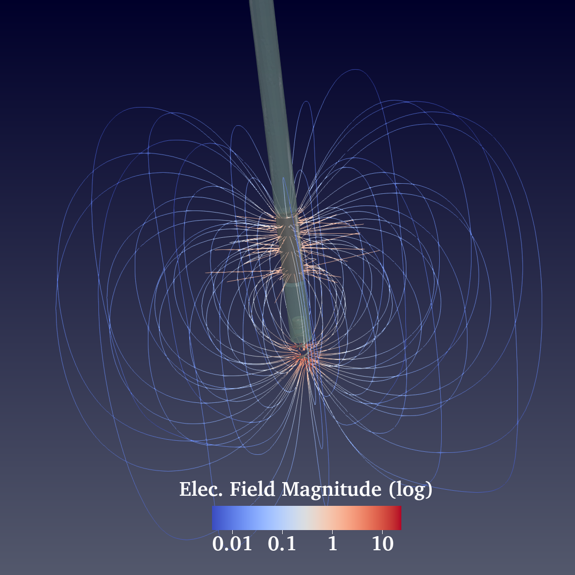
compute electric field : yes
# Pacemaker properties
# Stimulation
pacemaker stimulation amplitude : 5000.0
pacemaker stimulation duration : 2.0
pacemaker stimulation nspikes : 1.0
# Other phases of stim cycle durations
pacemaker
offset duration : 1.0
pacemaker period duration : 666.0
pacemaker switch duration : 0.122
pacemaker
ocd duration : 12.2
# Device electronics (microFarad, kOhm)
pacemaker internal cets : 9.3639
pacemaker internal cts : 10.6248
pacemaker internal rgnd : 0.018
pacemaker internal rpulse : 0.007
pacemaker internal rwa : 0.080
pacemaker internal rwc : 0.20
pacemaker internal rbig : 80.0
pacemaker internal rlittle : 0.005
# Contact properties
anode resistance: 2.0
anode capacitance: 18.74
# anode time constant: 37.48 # replace resistance or capacitance
cathode resistance: 0.03
cathode capacitance: 5.55
# cathode time constant: 0.1665 # replace resistance or capacitance
# Tissue
conductivity : CONSTANT -1 1. 0. 0. 0. 1. 0. 0. 0. 1.
# Solvers parameters
linear solver type : BICGSTAB
linear solver relative tolerance : 1.E-12
pde solver : FBE
pde time step : 0.01
# time step can be overriden by the pacemaker
pacemaker
offset time step : 0.01
pacemaker
pulse time step : 0.01
pacemaker switch time step : 0.01
pacemaker
ocd time step : 0.01
pacemaker waiting time step : 0.01
References
[1] Pannetier, V. et al. (2023). Modeling Cardiac Stimulation by a Pacemaker, with Accurate Tissue-Electrode Interface. In: Bernard, O., Clarysse, P., Duchateau, N., Ohayon, J., Viallon, M. (eds) Functional Imaging and Modeling of the Heart. FIMH 2023. Lecture Notes in Computer Science, vol 13958. Springer, Cham. https://doi.org/10.1007/978-3-031-35302-4_20
